
Key Takeaways
- Size for the spray equipment, not the compressor’s maximum pressure. Add the simultaneous air consumption of the guns and pneumatic auxiliaries, then compare the result with verified Free Air Delivery (FAD) at the required compressor working pressure. For the broader comparison with abrasive blasting, see the Peakroc® sandblasting and spray-painting sizing guide.
- A 6–8 bar compressor outlet is not a 6–8 bar HVLP spray-gun setting. Regulate and measure gun inlet pressure with the trigger open; the required inlet pressure and air-cap pressure depend on the actual gun.
- Oil and water must be controlled separately. Cooling, bulk-water separation, drying, coalescing filtration and, where specified, oil-vapor treatment serve different functions. The pressure dew point guide explains why water can still condense downstream of a separator.
- Paint defects require evidence, not guesswork. Fisheyes, blisters and poor atomization can involve dirty compressed air, but substrate preparation, coatings, spray-gun setup and booth conditions can produce similar symptoms. The oil carryover troubleshooting guide covers one possible upstream oil source.
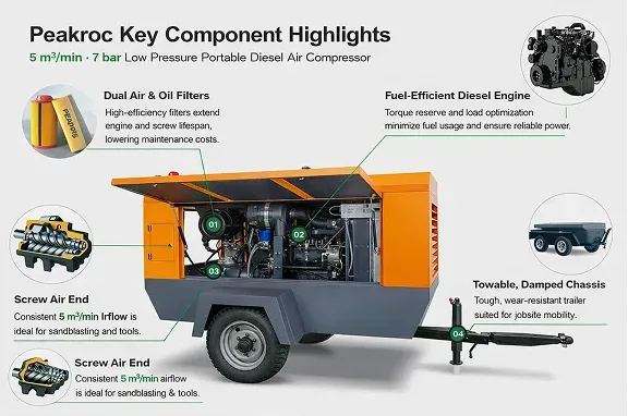
- Check the complete portable package. A 5 m³/min, 7 bar portable diesel compressor is an example of a mobile air source, not a ready-certified paint-air system. Use the compressor selection service to review airflow, pressure, duty and air-treatment requirements together.
A spray gun may have adequate compressor pressure on paper and still produce an uneven finish. During continuous spraying, an undersized hose or filter can reduce pressure at the gun. On a humid afternoon, water vapor can condense in a cooler hose. Oil aerosol or residual contamination can travel through a poorly maintained supply line.
These problems matter in mobile steel-structure coating, shipyard repairs, equipment refurbishment and industrial painting. The right question is not simply, “How many bar does the compressor produce?” It is whether clean, dry air reaches each active spray gun at the manufacturer’s required flow and dynamic pressure.
Why Spray Painting Needs a Different Air Supply from Sandblasting
Abrasive blasting generally requires substantial continuous airflow to accelerate particles. Air-atomizing spray painting usually consumes less air but can be more sensitive to its purity and pressure stability. A large compressor selected for blasting does not automatically deliver painting-grade air.
Conventional air spray, HVLP and compliant guns have different inlet pressures and air-consumption characteristics. Air-assisted airless equipment uses compressed air to shape or assist a high-pressure fluid spray. Pure airless systems may not need compressed air for atomization at all, although pneumatic pumps or other accessories can still consume air. Confirm the exact spray process before estimating compressor demand.
CFM/FAD: Calculate the Air Needed by Every Active Gun
Manufacturers specify spray-gun air consumption in CFM, SCFM or L/min at defined operating conditions. Many HVLP configurations consume substantial airflow despite their low air-cap pressure. Do not use an arbitrary “CFM per spray gun” value when the exact air cap, fluid setup and manufacturer data are available.
Example: A Four-Gun Mobile Coating Job
Assume four guns each require 20 SCFM, and the job also uses a pneumatic paint-feed or mixing device drawing 12 SCFM. With a provisional 20% design allowance for leaks and uncertainty:
Total airflow = (4 × 20 + 12) × 1.20 = 110.4 SCFM
Using 1 m³/min ≈ 35.3 CFM, this is approximately 3.13 m³/min of reference-volume airflow.
The example is illustrative, not a specification for a particular gun. Match the gun’s SCFM reference conditions with the compressor’s FAD rating before comparing figures.
The 20% allowance does not make pressure drop disappear. Hose and filter restrictions require a separate pressure check, and a desiccant dryer may consume additional purge air.
Five CFM/FAD Sizing Checks
- Record each gun’s actual air-cap and nozzle configuration, rated air consumption and required inlet pressure.
- Count the maximum realistic number of guns spraying at the same time.
- Include pneumatic pumps, agitators and other devices connected to the same supply.
- Include credible leakage, future-use and dryer-purge allowances without double-counting them.
- Compare required flow with verified compressor FAD at the selected working pressure, allowing for site temperature, altitude and duty cycle.
An oversized diesel machine can spend excessive time unloaded when supplying only one small spray gun. For a fixed booth with modest demand and reliable power, a properly treated electric compressor may be more economical. A portable diesel screw unit makes more sense when mobility, shared pneumatic loads or continuous field duty justify it.
6–8 Bar Supply vs HVLP Spray-Gun Pressure
The pressure at the compressor outlet, after the air-treatment train, at the gun inlet and at the gun air cap are four different measurements. Six to eight bar (approximately 87–116 psi) describes a common class of compressor supply pressure; it must not be applied directly to an HVLP spray gun.
HVLP refers to high-volume, low-pressure atomization, commonly limited to about 10 psi (0.7 bar) at the air cap. The gun inlet may require a higher value because the air passages reduce pressure internally. A regulator and a pressure gauge suitable for the gun are therefore essential. Use the gun manufacturer’s setting, never a universal HVLP inlet pressure.
Consider an illustrative supply operating at 7 bar. After distribution and treatment losses, the pressure available at the booth may be lower. The regulator then reduces it to the required gun inlet setting. If a narrow coupling or clogged filter creates a substantial drop while the trigger is open, the spray pattern can become unstable even though the compressor gauge looks normal.
Five Dynamic-Pressure Checks
- Measure pressure at the gun inlet while air is flowing, following its operating instructions.
- Compare the reading with the gun manufacturer’s recommended setting, not the compressor’s gauge.
- Inspect hose internal diameter, length, fittings and high-restriction quick couplings.
- Measure differential pressure across filters and dryers during peak demand.
- Test with all intended guns running, then correct restrictions before raising compressor discharge pressure.
Moisture and Oil Contamination: Build a Complete Treatment Train
A hot compressor discharge can hold considerable water vapor. As the air cools in a receiver, hose or metal pipe, moisture can condense into liquid droplets. A separator collects liquid water; it cannot remove all water vapor. The required pressure dew point describes the temperature at which water will begin condensing at the specified pressure.
For example, a refrigerated dryer delivering a pressure dew point near +3°C may be adequate when the downstream system stays comfortably warmer than that temperature and meets the coating specification. A colder outdoor line or more demanding process may need a lower dew point and another drying approach. Neither +3°C nor −40°C should be advertised as universally required for spray painting.
Oil contamination has several forms. Coalescing filters remove liquid oil aerosols and droplets when appropriately selected and maintained; ordinary particle filters cannot be expected to remove oil vapor. Where the total-oil specification requires vapor treatment, correctly protected adsorption media or another validated technology may be necessary.
A practical process may include:
Aftercooling → Bulk-water separation and drains → Dryer with its specified pre/postfilters → Final fine filtration and any required vapor control → Clean dedicated painting hose → Gun regulator
Component order depends on the equipment design.
Five Air-Treatment Checks
- Establish the coating supplier’s acceptable particle, water and oil limits at the point of use.
- Verify aftercooler performance, automatic drains and bulk-water separation under humid peak conditions.
- Select dryer capacity using actual inlet temperature, pressure, ambient conditions and corrected flow rating.
- Choose coalescing, particulate and oil-vapor filtration for the contaminants actually present; monitor element condition.
- Keep painting air hoses and branches separate from tool lubricators, and validate final air quality rather than relying on a filter label.
ISO 8573-1 expresses compressed-air purity using separate particle, water and oil classes. It does not impose one universal “paint-shop class.” The coating process should define the required classes, and testing should confirm performance at the gun supply point.
Fisheyes, Pinholes, Blisters and Poor Atomization
Visible coating defects are clues, not laboratory identification of a contaminant. Oil or silicone contamination can cause fisheyes or craters; moisture or dirt in air lines can contribute to defects including blistering. Yet poor surface cleaning, incompatible materials, excessive film thickness, solvent entrapment and incorrect spray technique may produce similar results.
| Observed defect | Possible compressed-air contribution | Other causes to rule out | Practical check |
|---|---|---|---|
| Fisheyes / craters | Oil aerosol, vapor or contaminated hose | Silicone, wax, grease, substrate contamination | Check air purity and compare with a properly prepared control panel |
| Blisters / bubbles | Moisture, oil or dirt reaching the coating | Humidity, solvent trapping, incompatible layers, excess film | Verify pressure dew point, drainage and coating procedure |
| Pinholes | Water or contamination affecting application | Outgassing, porous primer, excessive film thickness | Review air quality, substrate and cure conditions |
| Poor atomization / coarse droplets | Low dynamic gun pressure or insufficient airflow | Wrong fluid viscosity, nozzle, air cap or technique | Measure gun inlet pressure with trigger open |
| Uneven fan / striping | Pressure instability or restricted air supply | Blocked air-cap holes, incorrect gun setup | Check hose/fittings and inspect gun passages |
| Dirt nibs | Particles or corrosion from air line | Booth dust, tack-rag fibers, dirty workpiece | Compare filtered gun supply and booth cleanliness |
Five Defect-Diagnosis Checks
- Record whether defects occur at startup, during peak flow, after maintenance or in humid weather.
- Inspect the coating material, mix ratio, substrate cleaning and booth conditions before blaming compressed air.
- Measure dynamic gun pressure and evaluate spray pattern with the correct coating setup.
- Test water and oil contamination at the final paint-air outlet, especially if several guns show the same defect.
- Correct the verified source, prepare a clean test panel and document whether the defect recurs.
Do not attempt to correct fisheyes by automatically increasing spray pressure or adding unspecified coating additives. Follow the coating manufacturer’s rework and refinishing procedure.
Technical Field References: What Real Paint Shops Found
Field Reference 1: Moisture-Related Rework at a U.S. Coating Plant
A published manufacturing case describes a plant in Booneville, Mississippi, where water carried through compressed-air lines caused spots on finished metal and wood components. Two employees were dedicated to coating rework.
The plant replaced its ineffective drying arrangement with membrane drying and appropriate upstream filtration. Its maintenance manager reported that moisture-related rework stopped and the two workers were reassigned.
This was a supplier-associated case report, not an independently audited comparison, and the result should not be generalized to every dryer installation.
Field Reference 2: Air-Purity Monitoring in an Automated Paint Shop
A published automotive paint-system case describes the use of continuous and portable measurements for pressure dew point, oil vapor and particle concentration.
The objective was to verify the compressed air delivered to the painting process and identify contamination risks before coating defects occurred.
The report emphasizes visibility and process control; it does not establish a universal acceptable air class or publish a transferable defect-reduction percentage.
Field Reference 3: Wheel-Refinishing Air Quality Verification
A published wheel-refinishing workshop case describes monitoring oil vapor and solid particles in the paint-air supply.
The supplier reported more consistent finishes following measurement and control improvements. Because the source does not provide independently verified before-and-after reject rates, its useful lesson is the monitoring method rather than a numerical claim of guaranteed savings.
These references illustrate different needs: removing actual moisture, verifying overall paint-air purity and monitoring contaminants that may not be visible during spraying.
Five Checks Before Buying or Commissioning a Portable Painting-Air Package
- Application: Identify HVLP, conventional, compliant, electrostatic or air-assisted equipment and obtain the exact gun data sheets.
- Capacity: Calculate simultaneous SCFM/FAD demand, treatment losses and auxiliary airflow at the required pressure.
- Air purity: Agree on particle, water and oil limits, with acceptance testing at the final painting connection.
- Field operation: Confirm diesel ventilation and exhaust separation, ambient temperature, hose routing, drainage, noise and service access.
- Maintenance and safety: Define filter replacement, dryer checks, condensate disposal and a separate compliant breathing-air arrangement when supplied-air respirators are required.
Paint-spray air is not breathing air. Do not connect a supplied-air respirator directly to an ordinary oil-injected diesel compressor or assume that paint-quality filters meet occupational breathing-air requirements. Provide compliant breathing-air equipment and respiratory protection appropriate to the coating hazards and local rules.
Final Recommendation
Choose a portable spray-painting air system from the spray gun backward: gun airflow and dynamic pressure first, then piping, treatment capacity and verified compressor FAD. Keep moisture and oil controls distinct, and verify the actual quality of air at the paint booth.
A 6–8 bar mobile compressor may be a suitable supply source for a properly designed installation, but finish quality depends on more than its pressure rating. Stable gun pressure, correct drying, effective filtration, clean hoses and coating-process discipline are what turn compressed air into reliable painting performance.
FAQ
How much CFM does an HVLP spray gun need?
It depends on the model and air cap. Some HVLP setups require roughly 15–26 CFM, but the correct value is the manufacturer’s specified consumption at the required inlet pressure. Add the demand of all guns operating simultaneously.
Does a spray gun need 6–8 bar pressure?
Usually not at the gun. Six to eight bar may be a compressor supply rating. HVLP guns operate at much lower air-cap pressure and require a model-specific regulated inlet pressure measured during airflow.
Is a 5 m³/min, 7 bar diesel compressor enough for spray painting?
Its nominal flow is about 177 CFM, potentially enough for several guns on airflow alone. Final suitability depends on verified FAD, simultaneous demand, operating duty, pressure losses and properly sized drying and filtration.
Can an oil-injected screw compressor be used for spray painting?
Yes, if the complete system produces the required compressed-air purity. Its internal separator alone cannot guarantee removal of moisture, oil aerosols and oil vapor at the spray gun.
Will a water separator remove moisture from spray-painting air?
It removes separated liquid water, not all water vapor. A suitably selected and maintained air dryer is needed when the required pressure dew point cannot otherwise be achieved.
What causes fisheyes in a painted surface?
Oil or silicone contamination can cause fisheyes, but wax, grease, dirty surfaces and other coating-related factors can do so as well. Test the air and investigate surface preparation before assigning the cause.
What is ISO 8573-1 for spray painting?
It classifies compressed-air purity for particles, water and oil. The coating or equipment specification must set the acceptable classes; the standard does not prescribe one universal class for every spray-painting application.
Can painting-air compressors also supply respirators?
Not automatically. Supplied-air respirators require a separate system meeting applicable breathing-air quality, equipment and monitoring rules. Paint-air filtration alone is not sufficient proof of respirator safety.
Author

Mark Chen – Senior Mechanical Engineer, Peakroc®
Mark Chen is a senior mechanical engineer at Peakroc®, specializing in compressed air systems and drilling equipment for mining and construction applications. With over 15 years of field experience, he has led multiple projects on optimizing air delivery efficiency, equipment durability, and energy consumption.