
Key Takeaways
- A pipeline compressor is not one fixed machine class. Blowing, pigging, purging, drying and pneumatic testing can require very different pressure-flow combinations, so first understand how CFM, FAD, SCFM and ACFM relate to actual compressor capacity.
- Medium-pressure pipeline duties are often determined by both flow and pressure rather than pressure alone. The 10–15 Bar Medium-Pressure Portable Air Compressor Guide provides useful context for this range.
- Large pipelines may require several compressors working together because airflow can become the limiting factor. The 1100–1200 CFM High-Flow Portable Compressor Guide shows why FAD must be checked at the actual working pressure.
- Pipeline drying is an air-treatment problem as well as a compressor-sizing problem. When a specified low pressure dew point is required, the Refrigerated vs Desiccant Air Dryer Guide explains why dryer technology matters.
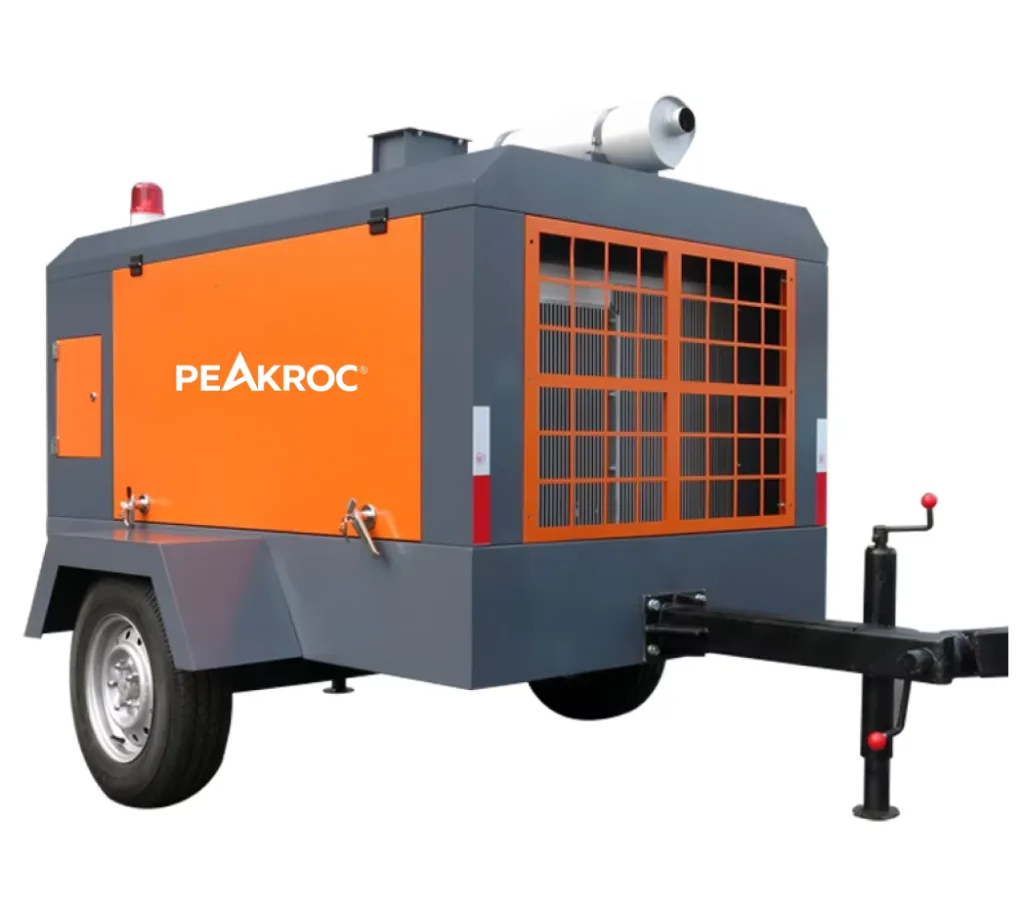
- Higher-pressure pipeline work should follow the approved engineering procedure, not the compressor’s maximum rating. A 15 m³/min / 18 bar Portable Diesel Air Compressor illustrates one useful pressure-flow class, but it does not define the correct operating or test pressure for every pipeline.
A request for “a compressor for pipeline work” is not enough to select a machine.
Compressed air may be used to blow loose debris from a new line, move a construction pig, displace an atmosphere with an approved purge medium, remove moisture after hydrotesting, or gradually pressurize a system during an engineered pneumatic test. These activities all involve compressed gas, but their compressor requirements are very different.
A better selection sequence is:
Pipeline Operation → Pipe Diameter & Length → Required Flow → Required Pressure → Air Quality → Completion Time → Site Conditions → Safety Procedure
The first engineering question is therefore not “How many bar?” or “How many CFM?” It is:
What must the compressed air actually accomplish inside the pipeline?
Different Pipeline Operations Need Different Compressor Priorities
Pipeline geometry gives the scale of the job, but the operation determines which compressor characteristic matters most.
| Pipeline Operation | Main Requirement | Main Selection Question |
|---|---|---|
| Blowing | High airflow with sufficient pressure | Can the required cleaning velocity be maintained? |
| Pigging | Controlled flow and differential pressure | Can the pig move continuously at the intended velocity? |
| Purging | Controlled volume displacement | Is the selected purge medium permitted and can the target composition be reached? |
| Drying | Dry airflow over sufficient time | Can the specified dew point be achieved? |
| Pneumatic testing | Controlled pressure increase | Can the approved test procedure be followed safely? |
For blowing, airflow often dominates because debris or water must be carried toward the discharge point. For pigging, pressure creates the driving force, but airflow is needed to continue increasing downstream volume as the pig advances. Drying is different again: a large airflow number is of limited value if the air itself contains too much moisture.
This is why pipeline diameter should never be used as a direct shortcut to compressor size.
Pipeline Volume, Flow and Pressure Must Be Read Together
For a cylindrical pipe, internal volume can be estimated from:
V = πD²L / 4
where D is internal diameter and L is pipeline length.
A 300 mm ID pipeline that is 1,000 m long contains roughly 71 m³ of internal volume. If the diameter doubles at the same length, the volume increases by approximately four times.
That volume is important for fill time, drying time and purging calculations, but it still does not tell you the required compressor.
For pipeline blowing, a useful first relationship is:
Q = A × v
where Q is airflow, A is the internal cross-sectional area and v is the desired air velocity.
A larger line therefore needs much more airflow to create the same internal velocity. Pressure is still required to overcome friction, fittings, elevation and discharge resistance, but selecting a higher-pressure compressor cannot compensate indefinitely for insufficient FAD.
Pigging adds another relationship:
F = Δp × A
The pressure differential across the pig acts over the pig’s effective seal area and creates the driving force. This is a useful first-pass concept, but real pig behavior also depends on seal friction, valve geometry, line condition, elevation, downstream backpressure, leakage and gas compressibility.
A simple V/Q calculation can help estimate how long it takes to introduce a certain free-air volume, but it should not be treated as an exact pig-travel-time formula. As pipeline pressure rises, compressor output can change, gas is compressed, and the system volume behind the pig continuously changes as the pig moves.
Pigging Requires Pressure and Flow Control, Not Maximum Pressure
A pig must have enough differential pressure to overcome resistance, but once movement begins, the objective is usually controlled travel rather than maximum acceleration.
If the differential pressure is too low, the pig may stop. If pressure continues building behind a stationary pig and the pig suddenly releases, it can accelerate rapidly. For that reason, compressor size should be matched to the pipeline and pigging procedure rather than simply choosing the highest pressure available.
Compressor operating behavior can provide useful field clues. If pressure reaches the compressor setpoint and the compressor unloads and stays unloaded, there may be little or no continuing volume increase behind the pig. That can indicate a stalled pig, insufficient driving force or another restriction. If the compressor repeatedly loads as pressure falls, volume may still be increasing, although leaks and intermittent pig movement can create similar behavior.
This is useful diagnostic information, but it is not a substitute for pressure monitoring, pig tracking and an engineered pigging plan.
Long or high-volume lines may need multiple compressors connected through a suitably sized manifold. The combined system must be evaluated at the actual backpressure because the nominal free-air rating at low pressure may not represent the output available during pigging.
Purging and Drying Need More Than Compressor Capacity
Purging begins with the process requirement, not the compressor.
Compressed air contains oxygen and therefore cannot be assumed to be suitable for inerting. Some cleaning or commissioning procedures may permit air, while natural-gas or other flammable-service pipelines may require nitrogen or another specified medium. The approved procedure must define what atmosphere is being displaced, what purge gas is allowed and what end condition must be reached.
Drying has a different objective. After hydrotesting, a pipeline can be free of visible standing water but still contain surface moisture and water vapor. The typical sequence may involve dewatering, pigging, dry-air circulation and dew-point verification.
The compressor therefore works as part of an air-treatment train rather than as a standalone machine:
Compressor → Aftercooler → Water Separator → Filtration → Dryer → Final Treatment → Pipeline
Each component needs adequate flow capacity. If a 30 m³/min compressor feeds a dryer capable of only 20 m³/min, the dryer becomes the bottleneck.
The drying target should also be measurable. “Dry air” is too vague. A requirement such as −20°C or −40°C pressure dew point provides a meaningful design target and helps determine whether refrigerated drying is sufficient or regenerative desiccant drying is necessary.
Pneumatic Testing Is a Stored-Energy Operation
Pneumatic pressure testing should be treated separately from normal pipeline blowing or drying because the system contains a large quantity of compressed gas.
Gas is compressible, so substantial energy can be stored as pressure increases. If a temporary plug, flange, closure or pipe section fails, that energy can be released very rapidly.
This is why the compressor should be viewed only as the pressure source. The compressor’s maximum rating does not establish the allowable test pressure.
A pipeline test using an 18-bar compressor is not automatically an 18-bar test.
The approved test procedure should define the test medium, target pressure, pressurization stages, hold periods, overpressure protection, controlled access, safe locations for personnel, venting and depressurization. Temporary piping, restraints and closures must also be suitable for the stored energy involved.
The distinction is important because an ordinary blowing operation and a closed pneumatic pressure test may use the same compressor but have very different risk profiles.
Field Experience & Project Lessons
This section separates several real-world examples from the general sizing guidance. The purpose is not to copy another project’s compressor size, but to understand what the operating experience teaches us about pipeline air-system design.
Field Experience 1: A 6-Inch, 15 km Pigging Problem
An engineering forum discussion described a 6-inch construction pig being pushed through a 15 km pipeline using a compressor rated at approximately 150 CFM with a maximum operating pressure of 125 psi. The operator reached the compressor’s maximum pressure but could not determine whether the pig had become stuck or whether compressor capacity was insufficient for the long line.
The discussion used F = pA to think about driving force and t = V/Q as a rough fill-time estimate. It also highlighted the value of watching compressor load/unload behavior and checking whether valves along the line were fully open.
Experience gained: the case shows why maximum compressor pressure is not enough to predict pigging performance. A small compressor may eventually produce high static pressure behind a stalled pig while still lacking the airflow needed for practical continuous movement. It also shows why the distinction between pressure available and volume changing behind the pig matters. For long lines, a compressor performance curve at increasing backpressure is much more useful than a single displacement number.
Field Experience 2: 96 km Pipeline Inspection Using a Multi-Compressor System
A documented pipeline inspection project involved approximately 96 km of pipeline. Several compressors, a nitrogen generator and related temporary equipment were assembled to support the operation. Nitrogen was first used as part of the gas-removal process, and compressed air was then used to propel the pig.
The reported operating system achieved approximately 24 bar with an airflow of around 258 m³/min, or more than 9,000 CFM. The project took about four weeks and included onsite technical support.
Experience gained: this project demonstrates that large-scale pigging can become a complete temporary compressed-air engineering project rather than a single-machine purchase. It also shows why purge gas and pig-driving gas may not be the same medium. For a long pipeline, compressor staging, manifolding, controls, temporary connections and technical support can matter as much as the individual compressor specifications.
Field Experience 3: Drying 2+ Miles of 42-Inch Pipeline
Another project involved more than ten pipeline drying runs, with the largest sections exceeding 2 miles of 42-inch pipe. The larger runs used four PTS1600 compressors, four dryers and four heat exchangers, together with the required temporary hoses, fuel systems and trailers.
The first major 2+ mile run was dried in under 11 hours.
Experience gained: this case shows that drying performance should be evaluated as a complete air-treatment system. The total compressor flow was only useful because the dryer and heat-exchanger capacity was scaled with it. Adding more compressor CFM while leaving dryer capacity unchanged would not have produced the same result. It also demonstrates why completion-time targets can materially change the size and number of machines required.
Field Experience 4: −40 Dew Point Under Freezing Conditions
A natural-gas metering-station project required hot, dry, 100% oil-free air and a target dew point of approximately −40°C / −40°F under cold-weather conditions. The temporary system used a 1,600 CFM compressor, 1,600 CFM desiccant dryer and an additional heat exchanger.
Ambient temperatures dropped below freezing, so the project team also had to manage heat loss and protect dryer components from freezing. Insulation and supplemental heating became part of the solution. The required drying condition was reached in less than 54 hours, compared with an initial expectation of roughly two weeks.
Experience gained: compressor airflow alone does not determine drying time. Air temperature, dew point, weather protection and dryer operating conditions can become equally important. In cold environments, a theoretically adequate compressor-and-dryer package can still underperform if valves freeze or heat is lost before the dry air reaches the pipeline.
These cases all point toward the same engineering principle:
Pipeline compressed-air performance comes from the complete system, not from the compressor nameplate alone.
How to Build the Compressor Package
Once the pipeline operation is clearly defined, compressor selection becomes much more structured.
For blowing, calculate the airflow needed to create the required internal velocity, then confirm that the compressor can deliver that FAD after system pressure losses. For pigging, estimate the required pressure differential and target pig velocity, then evaluate compressor output at the actual backpressure. For drying, combine pipeline volume, remaining moisture, required dew point and completion time with the available dryer capacity.
A useful RFQ comparison is:
| Project Information | Why It Matters |
|---|---|
| Pipeline operation | Determines whether flow, pressure or air quality dominates |
| Internal diameter | Determines area and internal volume |
| Total length | Determines volume and pressure loss |
| Elevation/profile | Can influence pig behavior and resistance |
| Required FAD | Defines compressor capacity |
| Required working pressure | Defines pressure class |
| Target pig velocity | Important for pigging |
| Completion-time target | Can increase required airflow significantly |
| Required dew point | Determines drying method |
| Oil/particle requirement | Determines compressor and treatment configuration |
| Site altitude/temperature | May affect compressor performance |
| Hose/manifold size | Can become a major system restriction |
The compressor package should then be checked as one flow path from air inlet to pipeline connection.
Common Selection Mistakes
- Choosing compressor size from pipeline diameter alone. Diameter does not describe line length, pig friction, drying target or pressure loss.
- Using maximum pressure as the main selection number. High pressure does not replace inadequate airflow.
- Treating
V/Qas an exact pigging calculation. It is useful for scale and initial timing, but not as a complete compressed-gas model. - Assuming compressed air can be used for every purge. Inerting requirements may require nitrogen or another approved gas.
- Calling air “dry” without specifying dew point. Dryness should have a measurable acceptance criterion.
- Ignoring dryer purge loss and treatment pressure drop. Net flow at the pipeline can be lower than compressor FAD.
- Undersizing temporary hoses and manifolds. High-flow systems can lose significant pressure before reaching the pipeline.
- Using compressor maximum pressure as pneumatic test pressure. Test pressure comes from the approved engineering procedure.
Practical RFQ Checklist
Before requesting a pipeline compressor package, provide:
- Operation: Blowing, pigging, purging, drying or pneumatic testing.
- Pipeline service: Water, gas, oil or other process medium.
- Internal diameter and total length.
- Elevation/profile: Particularly for pigging.
- Required FAD and pressure: If already calculated.
- Pig type and target velocity: Where applicable.
- Required completion time.
- Required final pressure dew point: For drying.
- Oil and particulate requirements.
- Site altitude and ambient temperature.
- Temporary hose and manifold size.
- Standby or redundancy requirements.
- Approved testing/commissioning procedure: Where applicable.
If FAD is not known, provide the pipeline geometry and operation instead of guessing compressor size.
For example:
42-inch pipeline, 3 km long, post-hydrotest dewatering and drying, required final PDP −40°C, maximum ambient temperature 35°C, with drying required within the commissioning schedule.
That is a much stronger starting point than:
“Please quote a pipeline compressor.”
Final Recommendation
Blowing, pigging, purging, drying and pneumatic testing may all use portable compressed air, but they should not be treated as one application.
For blowing, airflow and internal velocity usually drive compressor size.
For pigging, pressure differential creates the driving force while airflow determines whether the pig can continue moving through the increasing pipeline volume.
For purging, the approved purge medium and acceptance condition come before compressor selection.
For drying, compressor FAD must be matched with dryer capacity, temperature management and the required dew point.
For pneumatic testing, the governing engineering procedure determines pressure, test medium and safety controls.
The most useful sizing sequence remains:
Operation → Pipeline Geometry → Flow → Pressure → Air Quality → Completion Time → Site Conditions → Temporary Air System
Do not select a pipeline compressor from maximum pressure or pipe diameter alone.
Select a complete system capable of delivering the required:
FAD + pressure + air quality
at the actual pipeline connection.
FAQ
How do I size an air compressor for pipeline blowing?
Start with the internal pipe diameter and the required cleaning velocity. Determine the airflow needed through the cross-sectional area, then estimate the pressure required to overcome friction, fittings and other system resistance.
How do I know whether a pig is stuck or the compressor is too small?
Compressor loading behavior and pressure changes can provide clues, but they are not conclusive. A proper assessment should compare pig-driving pressure, expected friction, line resistance, compressor output at actual backpressure and evidence that the downstream volume is changing.
Can I calculate pigging time from pipeline volume divided by compressor CFM?
V/Q can provide a useful first-pass estimate of free-air fill time, but it is not an exact pig-travel-time equation because gas is compressible and pigging involves changing volume, friction, backpressure and variable compressor output.
Is compressed air suitable for pipeline purging?
Only if the approved project procedure permits it. Where inerting or oxygen control is required, nitrogen or another specified gas may be necessary.
What dew point is required for pipeline drying?
There is no universal value. The required final pressure dew point comes from the commissioning specification and may vary considerably by pipeline service.
Is airflow or pressure more important for pipeline drying?
Both matter, but drying is often more sensitive to airflow, dew point and air temperature than to very high pressure. The compressor still needs enough pressure to move the required dry-air flow through the complete temporary system.
Can compressor maximum pressure determine pipeline pneumatic test pressure?
No. Compressor pressure rating describes equipment capability. The approved engineering procedure and applicable design requirements determine the test pressure.
Author

Mark Chen – Senior Mechanical Engineer, Peakroc®
Mark Chen is a senior mechanical engineer at Peakroc®, specializing in compressed air systems and drilling equipment for mining and construction applications. With over 15 years of field experience, he has led multiple projects on optimizing air delivery efficiency, equipment durability, and energy consumption.