
Key Takeaways
- Match the blower, not just the duct. Compressor pressure and Free Air Delivery (FAD) must meet the cable-blowing machine’s requirements at its inlet. The Peakroc® CFM/FAD guide explains how to compare airflow ratings.
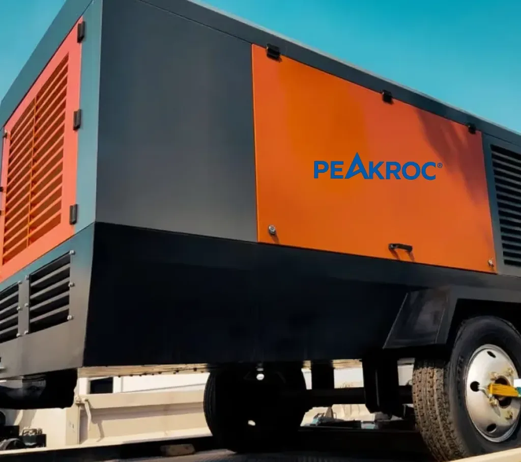
- 7–14 bar is a useful discussion range, not a universal setting. Small microduct systems can use very little air, while high-flow systems may require hundreds of CFM. The Peakroc® 10 m³/min, 10 bar compressor illustrates a medium-pressure capacity class, subject to the blower’s limits.
- Duct clearance and route condition matter as much as compressor size. Cable-to-duct fill ratio, bends, couplings, lubrication and leakage affect achievable installation distance. A 13 m³/min, 13 bar portable compressor is an option to evaluate only when the required airflow and regulated pressure justify it.
- Air quality is part of the specification. Hot, wet or contaminated compressed air can disrupt cable installation; an aftercooler, separator, filtration or dryer may be necessary. See the Peakroc® portable compressor moisture-control guide for treatment principles.
Cable blowing uses a mechanical feeder and moving compressed air to install optical fiber through an underground duct. An adequately sized compressor helps the cable travel with less friction and less reliance on pushing force alone. Yet a machine that delivers enough pressure at its outlet can still underperform when the blower receives inadequate air, the duct is restricted or moisture accumulates along the route.
For contractors, the practical task is to match airflow, working pressure, duct geometry and air quality under real jobsite conditions. Selecting the largest diesel compressor available is rarely a substitute for checking the blowing equipment and route.
How Compressed Air Moves Fiber Cable
A cable-blowing machine feeds cable into a duct using controlled belts or wheels. Compressed air flows around the cable and creates distributed drag that helps carry it forward. The blowing machine still supplies mechanical push, but the air reduces the force that must be transmitted along the cable over long distances.
This process differs from simply pressurizing a closed pipe. Air must move continuously through the available space between cable and duct. Too little flow can limit assistance; excessive pressure can damage couplings, duct or cable if equipment limits are ignored. Installation length also depends on bend radius, cable stiffness, lubrication, duct cleanliness and the equipment’s push-force controls.
Duct Diameter, Cable Fill Ratio and Route Length
Compressor demand often increases with larger duct passages, but nominal duct size alone is not a design input. Confirm the inside diameter, cable outside diameter and equipment manufacturer’s approved combination. A commonly used diameter-based fill ratio is:
Fill ratio (%) = Cable outside diameter ÷ Duct inside diameter × 100
For a 9 mm cable in a 14 mm internal-diameter duct, the fill ratio is 64.3%. This is not the fraction of duct cross-sectional area occupied by the cable. Published guidance commonly targets around 50–80% for some microcable systems, but the permitted combination must come from the actual cable and duct specifications. At high fill ratios, reduced annular clearance can restrict useful airflow.
Five Duct Details to Verify
- Actual duct inside diameter, material and approved pressure rating.
- Cable outside diameter, construction, minimum bend diameter and push-force limit.
- Route length, bends, elevation changes and intermediate access points.
- Duct cleanliness, coupler sealing, leakage, existing water and obstructions.
- Approved cable-to-duct combination and lubrication procedure.
Proper cleaning, duct proofing and compatible lubrication can be more productive than increasing compressor capacity. A failed duct pressure or passage test should be resolved before cable installation, following the equipment manufacturer’s approved procedure.
What Pressure Does Fiber Cable Blowing Need?
Many air-assisted systems work within approximately 7–14 bar, but this should not be used as a universal operating instruction. Some equipment guidance describes around 8–12 bar for standard conduits and approximately 10–12 bar for certain microduct installations. Other machines allow different pressure ranges, including higher maximum ratings. The lowest-rated component—blower, duct, hose or coupler—sets the safe system limit.
The pressure displayed at the compressor may exceed the pressure reaching the blower because hoses, aftercoolers, filters and fittings create resistance. A preliminary pressure balance is:
Required compressor pressure ≈ Required blower inlet pressure + delivery-system pressure loss
For example, if the blowing machine needs 9 bar at its inlet and measured or calculated upstream losses are 0.7 bar at the required flow, the compressor must supply about 9.7 bar. This illustrative figure does not include additional allowances or establish that every 10-bar compressor will be adequate. Verify the actual blower inlet pressure during operation; use approved pressure regulation and protection rather than exposing the blower to a compressor’s maximum discharge pressure.
Five Pressure Checks
- Confirm the blowing machine’s recommended inlet operating pressure.
- Identify the maximum permitted pressure of every connected component.
- Estimate losses through hoses, separators, filters, coolers and couplings.
- Verify stable compressor regulation at the required airflow and pressure.
- Measure pressure at the blower during a representative installation.
CFM/FAD: Matching Air Delivery to the Blower
CFM and m³/min are flow units; FAD describes delivered compressor capacity under defined reference conditions. For unit conversion, 1 m³/min ≈ 35.3 CFM. This conversion does not make a theoretical displacement rating equivalent to measured FAD, nor does it make airflow ratings at different pressures interchangeable.
Public equipment guidance shows why a single CFM recommendation is unreliable. Small blowing machines can specify approximately 7–18 CFM, while high-flow equipment can require around 280–424 CFM. Broad conduit guidance cites roughly 10–60 CFM for 5.5–14 mm microducts, 100–375 CFM for 16–20 mm microducts, and 150–425 CFM for 1–2-inch conduits. These are planning references rather than guaranteed demands for every duct. The exact blower and cable combination takes precedence.
Example: A Blower Requiring 375 CFM
Suppose the selected blower needs 375 CFM at its approved inlet pressure. The flow converts to approximately 10.62 m³/min. A compressor rated at 10 m³/min FAD represents about 353 CFM on a comparable basis and would fall short of the specified demand, even if its pressure were adequate. A larger airflow class may be appropriate, provided the manufacturer verifies FAD at the working pressure and the air-treatment package does not create unacceptable losses.
Equipment lists sometimes use rounded marketing CFM values. Before purchasing, request the rated FAD, measurement basis and operating pressure rather than assuming figures in different brochures describe identical capacity.
Five Airflow Selection Checks
- Use the blower manufacturer’s CFM or L/min demand, not only duct size.
- Confirm airflow reference conditions and guaranteed FAD at working pressure.
- Include other simultaneous pneumatic loads and treatment-system air consumption.
- Consider altitude, ambient temperature and continuous-duty performance.
- Avoid oversizing that causes unnecessary diesel fuel consumption and idle time.
More compressed air cannot overcome a damaged coupling, excessive cable push force or a blocked duct. Airflow should be increased only within approved operating limits and after identifying what restricts the installation.
Why Aftercooling and Dry Air Matter
Compressing air raises its temperature. As hot air cools in an aftercooler or buried duct, water vapor can condense, leaving liquid water that increases friction or causes problems in cold weather. Contaminants and lubricant carryover may also affect cable-handling equipment and duct cleanliness.
An aftercooler lowers air temperature, a moisture separator removes condensed liquid, and a dryer reduces remaining water vapor when a specified pressure dew point is needed. These components do different jobs. An aftercooler alone is not a dryer, and an oil-injected compressor’s internal separator does not guarantee oil-free delivery.
Five Air-Quality Checks
- Confirm the maximum allowable blower-inlet air temperature.
- Size the aftercooler for actual flow, pressure and ambient temperature.
- Verify liquid-water separation, drainage and condensate handling.
- Specify oil/particle filtration and drying where required by the project.
- Include pressure drop through all treatment components in compressor sizing.
In warm or humid conditions, cooling and separation may materially affect installation reliability. In freezing conditions, a dryer may be essential. The appropriate treatment level should follow the cable and blowing-machine manufacturer’s guidance, not an assumed universal air-quality class.
Troubleshooting Slow or Interrupted Cable Blowing
When cable movement slows, check measured pressure at the blower and the delivered airflow before blaming compressor horsepower. Duct bends, air leakage, unsuitable lubrication or cable stiffness may produce symptoms similar to insufficient air capacity.
| Symptom | Possible cause | First check |
|---|---|---|
| Slow movement from the start | Low FAD, insufficient blower pressure, duct friction | Verify inlet pressure/flow and duct preparation |
| Compressor gauge normal, blower pressure low | Hose, filter or dryer restriction | Measure pressure drop across delivery components |
| Speed declines with distance | Bends, friction, air leakage, push-force limit | Inspect route, seals and cable-feed settings |
| Water appears at duct outlet | Inadequate cooling, separation or drying | Inspect aftercooler, drains and dew point |
| Cable stalls at a bend | Duct obstruction or excessive bending | Stop, inspect route and follow approved recovery procedure |
| Couplings leak or detach | Seal fault or excessive pressure | Isolate system and verify component pressure ratings |
Do not compensate for a stalled cable by forcing the feeder or increasing pressure beyond the approved limits. Depressurize safely before disconnecting any component.
Technical Field References
1. Long-distance installation in Germany. A published 2024 field report describes a 288-fiber cable blown 1,842 m west of Frankfurt without interruption or cable damage. After an initial section, the crew increased air pressure to 14 bar, with a reported feed speed of 65 m/min. The account illustrates what a matched cable, route, machine and air system can achieve, but it does not publish a complete compressor FAD test; 14 bar is not a universal setting.
2. Microcable engineering trials. A 2025 cable-manufacturer technical note reports field results reaching 2,000 m and installation speeds up to 150 m/min under favorable conditions. It describes 915–1,520 m as a more realistic target for many installations and emphasizes fill ratio, duct condition and cooling. Those outcomes are cable/system trial results, not performance guarantees for any portable compressor.
3. Dry-air field package in Western Canada. A supplier-published project describes a portable compressor paired with an aftercooler, filtration and desiccant dryer for underground cable installation in freezing conditions. The supplier reports fewer moisture-related interruptions, but does not provide independently verified before-and-after productivity or dew-point results. The case supports checking air treatment without turning supplier claims into guaranteed savings.
Compressor Selection and RFQ Checklist
For small FTTH drops, a compact compressor may be more suitable than a large diesel package. Medium-flow portable screw compressors are relevant when blowing equipment requires hundreds of CFM and utility power is unavailable. Pressure rating must still match blower inlet requirements after losses, and every higher-pressure machine must be regulated to the approved system limit.
Five Details to Include in an RFQ
- Cable OD, duct ID, fill ratio and approved duct pressure rating.
- Blowing-machine model, required FAD and regulated inlet pressure.
- Route length, bends, elevation changes and simultaneous operations.
- Ambient conditions, air temperature, filtration and drying requirements.
- Compressor duty cycle, site altitude, transport needs and country of use.
For instance, an RFQ describing 350 CFM at 9 bar at the blower, a 40 mm ID duct, a 20 mm OD cable and a 1,200 m route is more useful than asking for a generic 10-bar compressor. A supplier can then assess package FAD, pressure loss and treatment requirements. At the same time, a large diesel unit operating mostly unloaded may increase fuel cost without improving installation speed.
Final Recommendation
Start with the actual blower and cable-to-duct pairing, not the compressor’s largest advertised number. Confirm FAD at working pressure, route and fill ratio, then allow for realistic air-delivery losses and the specified air-treatment equipment. The 7–14 bar range is relevant to many jobs but must never override manufacturer pressure limits. A reliable system supplies clean, dry-enough air at stable pressure and flow without unnecessary capacity or risk to the cable.
FAQ
What size compressor is needed for fiber optic cable blowing?
It depends on the blower, duct ID, cable OD and route. Equipment requirements range from tens to several hundred CFM. Select verified FAD at the intended working pressure.
Is 10 bar enough for cable blowing?
For some systems, yes. Verify required pressure at the blower after delivery losses and never exceed the rated pressure of the weakest component.
How much CFM does a 16–20 mm microduct need?
Broad planning guidance cites about 100–375 CFM, but actual requirements depend on the specific blower, cable and duct. Do not size the compressor from duct diameter alone.
Can a 13-bar diesel compressor be used?
Possibly, if its FAD is adequate and it has approved regulation and protection. The blower and duct must not receive more than their permitted pressure.
How is cable fill ratio calculated?
Divide cable outside diameter by duct inside diameter and multiply by 100. This is a diameter ratio, not an area-fill percentage.
Do cable-blowing compressors require an air dryer?
Not always. Cooling and liquid-water separation may suffice for some conditions, while freezing or moisture-sensitive installations may require a dryer.
What is the difference between CFM and FAD?
CFM is a flow unit. FAD describes actual delivered compressor capacity on a defined reference basis, so compare FAD at the required working pressure.
Why does blowing slow down even when the compressor pressure is normal?
Possible causes include low actual airflow at the blower, delivery-line pressure loss, leaking couplings, duct friction, moisture or unsuitable cable geometry.
Author

Mark Chen – Senior Mechanical Engineer, Peakroc®
Mark Chen is a senior mechanical engineer at Peakroc®, specializing in compressed air systems and drilling equipment for mining and construction applications. With over 15 years of field experience, he has led multiple projects on optimizing air delivery efficiency, equipment durability, and energy consumption.