
Key Takeaways
- Select the compressor from the blower, duct, cable, and route requirements together. The blower model alone does not determine the required airflow.
- Traditional telecom ducts may need high airflow at approximately 7–10 bar, while some small microduct systems need less airflow but pressure closer to 10–15 bar.
- Compare verified Free Air Delivery at the required pressure, not maximum pressure and maximum CFM stated at different operating points.
- Long routes, large ducts, bends, elevation changes, leaks, and hot weather can increase the practical airflow requirement.
- Cable-blowing air should normally be clean, dry, and aftercooled. Hot or wet air can increase friction, create condensation, and affect cable or duct materials.
- A fixed-pressure screw compressor may suit one standard blowing machine. A variable-pressure compressor is more useful for fleets working with several duct and cable combinations.
- Diesel, electric, and battery-powered portable compressors can all be suitable. The correct power source depends on mobility, electricity availability, emissions, noise, operating hours, and project location.
- For a final selection, use the blower manufacturer’s pressure and airflow data as the primary technical reference.
Fibre optic cable blowing uses compressed air and controlled mechanical feeding to install cable through underground ducts and microducts.
The blowing machine pushes or drives the cable forward while a high-speed air stream reduces contact and friction between the cable jacket and the duct wall. Compared with pulling alone, this method can reduce cable tension and support longer installation sections when the cable, duct, route, lubrication, and compressed-air supply are correctly matched.
The portable compressor is therefore not just a power source. It is part of the installation system.
Too little airflow can limit speed and distance. Insufficient pressure can prevent the system from overcoming route resistance. Excessive pressure, uncontrolled feed force, hot air, or wet air can also create installation problems.
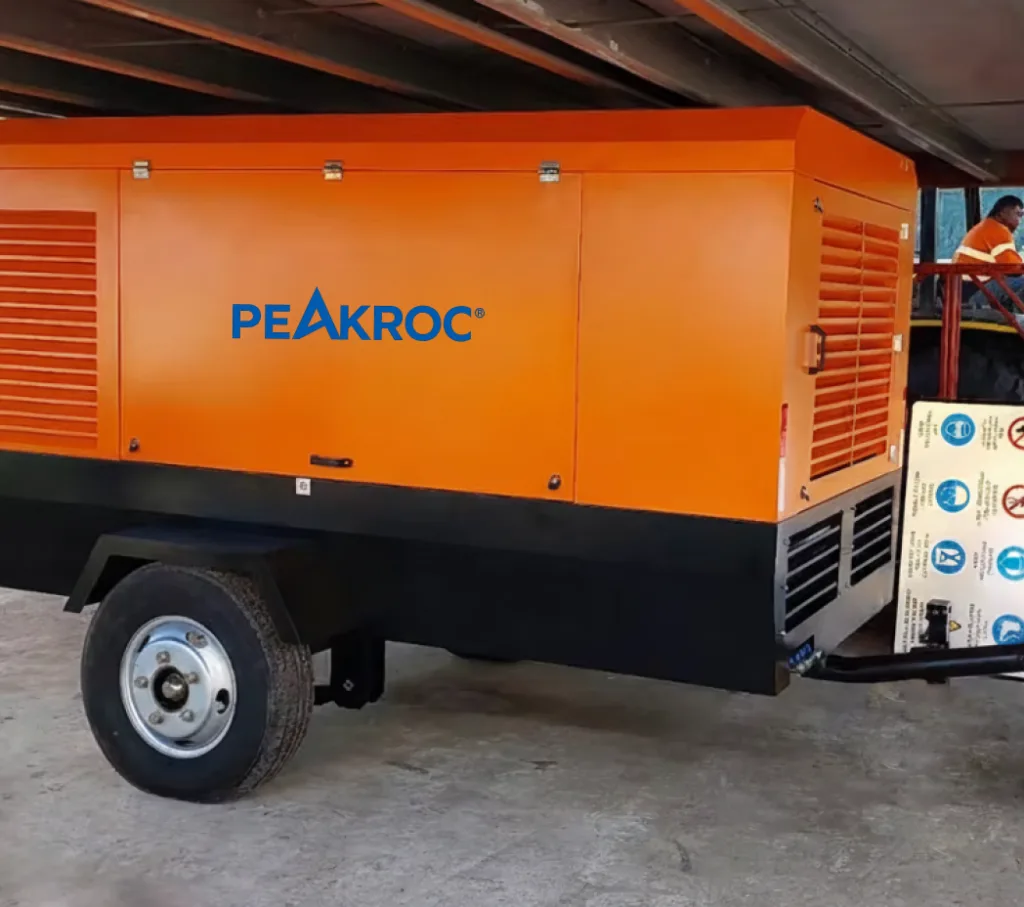
Peakroc® supplies portable diesel screw air compressors for telecom construction and other mobile compressed-air applications. Final selection should begin with the blowing-machine specifications and site conditions rather than choosing a compressor solely from its bar or CFM rating.
How Fibre Optic Cable Blowing Works
A typical installation system contains:
- A portable air compressor
- An aftercooler and moisture separator
- Air hoses and suitable couplings
- A fibre cable blowing machine
- Seals matched to the duct and cable
- Cable reel and reel stand
- Duct lubricant where specified
- Distance, speed, and pushing-force controls
The blowing machine introduces the cable into the duct while compressed air travels along the available space around the cable. The airflow helps support the cable and reduces the effective friction acting along the installed length.
Atlas Copco identifies pressure, FAD, energy efficiency, and compressed-air quality as the four main compressor-selection parameters for cable blowing. It also notes that FAD should be determined primarily by the duct and installation conditions rather than by the blowing machine’s physical size.
The compressor must maintain sufficient flow while the system is under load. A receiver tank may help stabilise short fluctuations, but it cannot compensate for a continuous airflow shortage.
Why One Universal Compressor Size Does Not Exist
The reference page from Power Energy provides a useful starting framework by dividing applications according to microduct or casing-pipe diameter and assigning different airflow and pressure classes. Its examples range from approximately 0.8–2.5 m³/min for smaller ducts to around 7–11 m³/min for larger casing pipes. It also distinguishes standard fixed-pressure screw compressors from variable-pressure systems.
Those values should not be copied as universal rules.
Actual demand depends on:
- Blower manufacturer and model
- Duct inside diameter
- Cable outside diameter
- Clearance between cable and duct
- Duct length and internal condition
- Number and radius of bends
- Elevation changes
- Ambient temperature
- Leakage at seals and couplings
- Installation speed target
- Lubrication method
Two projects using the same cable can require different compressors when one route is short and straight while the other contains multiple bends or elevation changes.
Condux, for example, publishes substantially different requirements for its product families. The Gulfstream 150 and 300 are listed for approximately 7–10 bar and 185–500 CFM, depending on duct and fibre size. The smaller Gulfstream 400XL microduct systems operate at approximately 10–15 bar but may require only around 10–35 CFM.
This illustrates a critical selection principle:
Large traditional ducts may require more airflow, while small microduct systems can require less airflow but higher pressure.
Pressure and FAD Must Be Compared Together
Pressure and airflow perform different functions.
Pressure helps overcome system resistance and maintains the force needed to move air through the duct. FAD determines how much usable air the compressor continuously delivers at the selected pressure.
A compressor may reach 14 bar but provide too little FAD for a large traditional duct. Another machine may provide high airflow at 7 bar but fail to operate a microduct blower that requires 12–14 bar.
The quotation should therefore state:
| Required performance item | Why it matters |
|---|---|
| FAD at the selected working pressure | Confirms usable airflow during blowing |
| Adjustable pressure range | Shows whether one machine can support different blowers |
| Maximum continuous pressure | Confirms the machine can sustain the required setting |
| Flow at minimum and maximum pressure | Prevents comparison of unrelated catalogue figures |
| Outlet size and number | Determines hose and manifold compatibility |
| Maximum ambient temperature | Confirms cooling capacity |
| Altitude correction | Accounts for reduced air density and engine performance |
| Aftercooler pressure drop | Confirms the air reaching the blower remains adequate |
Atlas Copco’s B-Air 185-12 provides a practical example of pressure-flow variation. The battery-powered unit is rated over a 5–12 bar range, with published flow changing from approximately 5.4 to 3.7 m³/min across that range. This demonstrates why the maximum airflow and maximum pressure should not be treated as one simultaneous operating point.
For projects using more than one blower type, a variable-pressure compressor can improve fleet utilisation. For a contractor using one standard blower at one pressure, a fixed-pressure model may be less complex and more economical.
Traditional Duct and Microduct Requirements
Traditional Telecom Ducts
Traditional duct systems commonly have more internal area around the cable, but their larger cross-section can require substantial airflow to establish the necessary air movement.
Condux lists approximately 185–375 CFM for selected traditional-duct applications, with pressure around 7–10 bar. Its larger Gulfstream equipment can require up to approximately 500 CFM depending on duct and cable size.
This places many traditional installations within the range of medium portable screw compressors.
Potential Peakroc directions may include:
- 7 m³/min, 10 bar portable diesel compressor
- 10 m³/min, 10 bar portable diesel compressor
- 10 m³/min, 13 bar portable diesel compressor
These are product directions rather than automatic recommendations. The selected model must provide the blower’s required FAD after accounting for the aftercooler, hoses, elevation, temperature, and operating pressure.
Microduct and Microcable Systems
Microduct equipment can have very different requirements.
Some compact systems operate with relatively low flow because the duct cross-section is small, but pressure may reach 10–15 bar. Condux lists approximately 10–35 CFM for selected Gulfstream 400XL configurations at 10–15 bar.
This creates a common sizing mistake: selecting a large 7-bar compressor because it has abundant CFM, even though the blower needs higher pressure.
For microduct work, the contractor should confirm:
- Maximum permitted pressure of the duct
- Required blower pressure
- Minimum and maximum airflow
- Cable and microduct diameter
- Seal configuration
- Maximum feed force
- Cable-jacket limitations
- Required air temperature
Do not assume that a larger compressor is safer. Excessive capacity can make pressure and airflow harder to control unless the compressor has accurate regulation and the blowing system includes suitable protection.
How Duct and Cable Diameter Affect Compressor Demand
The difference between duct inside diameter and cable outside diameter creates the annular space available for airflow.
When the space is too small, resistance increases and the system may require higher pressure. When the duct is much larger, a greater volume of air may be needed to establish useful air velocity along the route.
The best compressor cannot correct a poor cable-to-duct combination.
Before sizing the compressor, record:
Duct inside diameter
Cable outside diameter
Duct material
Cable weight per metre
Cable stiffness
Route length
Number and radius of bends
Elevation profile
The blower manufacturer may provide a compatibility chart or sizing software for these values.
Power Energy’s reference table also reflects the relationship between duct diameter and compressor demand: its suggested airflow increases from below 1 m³/min for an 8 mm microduct to as much as 7–11 m³/min for 32–50 mm casing pipe.
The exact thresholds vary by blower, but the direction is sound: larger duct systems generally move the project toward higher airflow classes.
How Route Length, Bends, and Elevation Change the Requirement
A straight, clean, level duct is easier to blow than a route containing tight bends, joints, contamination, and elevation changes.
Longer routes increase the cumulative resistance acting on the cable. Bends create additional contact and can concentrate pushing force. Uphill sections add gravitational resistance, while downhill sections may require careful speed control.
Atlas Copco states that longer blowing distance normally requires greater airflow and that pressure and flow should be adjusted to maintain stable cable movement.
The reference article from Power Energy mentions potential installation distances of approximately 1,500–2,500 metres with a well-matched blower and compressor. That range should be treated as an application claim, not a guaranteed compressor capability. Achievable distance depends on the complete installation system and route condition.
A useful planning approach is to separate the route into sections and identify:
- Straight-section length
- Bend locations and radii
- Intermediate access chambers
- Duct joints
- Elevation changes
- Possible water or contamination
- Planned blowing direction
- Whether tandem blowing or intermediate assistance is possible
A project that is difficult in one uninterrupted section may be more reliable when divided into planned stages.
Why an Aftercooler Is Important
Air temperature rises during compression. Without adequate cooling, hot compressed air can enter the duct and blowing equipment.
The Power Energy reference article places strong emphasis on aftercooling, warning that excessive air temperature can affect cable and duct materials. It recommends selecting a compressor with an integrated or external compressed-air cooler.
An aftercooler is a heat exchanger installed after compression. As the air cools, part of its water vapour condenses into liquid. A separator and drain then remove much of that condensate.
Atlas Copco explains that an aftercooler should normally be installed close to the compressor and is commonly combined with a moisture separator and automatic drain. It also notes that discharged air temperature after effective cooling is often approximately 10°C above the cooling medium, although actual performance depends on design and conditions.
An aftercooler performs two important functions for fibre blowing:
- It reduces the temperature of the air entering the duct.
- It enables bulk moisture to condense and be separated before reaching the cable.
The supplier should state the expected compressed-air outlet temperature at the project’s maximum ambient temperature—not only under mild test conditions.
Moisture Control and Dry-Air Requirements
Cooling hot compressed air produces condensate. That water must be removed.
Moisture in the duct can:
- Increase friction
- Dilute or disturb cable lubricant
- Create unstable blowing performance
- Collect in low points
- Contaminate seals and equipment
- Form condensation further along the route
Atlas Copco describes clean, dry, aftercooled air as essential for consistent cable blowing, particularly over longer distances.
A practical mobile air-treatment arrangement may include:
Compressor
→ Aftercooler
→ Moisture separator
→ Automatic or manual drain
→ Suitable filter
→ Air hose
→ Cable blower
An aftercooler and separator remove bulk liquid water, but the air leaving them may still be saturated with moisture. A dryer may be required when the project specifies a lower pressure dew point, when ambient humidity is high, or when condensation risk remains unacceptable. Atlas Copco notes that aftercoolers provide an initial moisture-removal step rather than complete drying.
The contractor should clarify whether the blower manufacturer requires:
- Aftercooled air only
- Aftercooler plus separator
- Additional coalescing filtration
- Refrigerated drying
- Desiccant drying
- A specified pressure dew point
Every treatment component introduces some pressure drop, so the compressor must be sized for the pressure and airflow required after treatment.
Should the Compressor Be Oil-Free?
Oil-free compression may be valuable for sensitive telecom work, but it is not automatically mandatory for every fibre-blowing project.
An oil-injected screw compressor normally uses an internal separator to remove most compressor lubricant from the discharged air. Additional filtration may be used where the project has strict contamination limits.
Oil-free or battery-driven equipment may be preferred when:
- The project specification requires oil-free air
- Work occurs in sensitive urban environments
- Local exhaust emissions are restricted
- Noise limits are strict
- Cable or duct contamination must be minimised
- Public tender criteria reward lower-emission equipment
The air-quality requirement should be obtained from the blower, cable, duct, or project specification. Do not use “oil-free” as a substitute for specifying moisture, particle, and hydrocarbon limits.
Diesel, Electric, or Battery-Powered Compressor?
Diesel Portable Compressor
A diesel compressor is practical for remote routes without stable electricity. It provides independent mobility and can support long shifts when fuel logistics are available.
Its disadvantages include exhaust emissions, engine noise, fuel handling, and engine maintenance.
Electric Portable Compressor
An electric compressor can reduce local emissions, noise, and operating cost where suitable grid power is available.
The contractor must confirm voltage, frequency, cable length, starting current, generator compatibility, and whether the electrical supply is available at each access chamber.
Battery-Powered Compressor
Battery-powered compressors are increasingly relevant for urban telecom construction.
Atlas Copco reports that Dutch contractors APK Group CIAG and Ravesteijn Infra & Telecom adopted B-Air 185-12 battery-powered compressors for fibre cable and conduit blowing. The companies valued low noise, zero local exhaust emissions, and independence from an external electrical connection. One contractor also reported that the equipment helped support success in a public tender. This is a manufacturer-reported case, so it should be treated as an application example rather than a universal economic guarantee.
The B-Air example shows that power-source selection can influence more than energy cost. It may affect tender eligibility, work-hour restrictions, urban access, and operator conditions.
Fixed-Pressure or Variable-Pressure Screw Compressor?
A fixed-pressure screw compressor is normally suitable when the contractor uses one blower with consistent requirements.
A variable-pressure compressor becomes more attractive when the fleet handles:
- Multiple duct sizes
- Microduct and traditional duct
- Different blowing-machine models
- Short and long routes
- Telecom and other pneumatic applications
- Changing pressure and flow requirements
Power Energy describes variable-geometry screw compressors as particularly useful for larger companies operating multiple tools and blowers, while noting that the higher investment may not be justified for a contractor using one fixed application.
A real-world example comes from an FTTH project in Erbil, Iraq. Atlas Copco reports that an XAHS 400 with PACE control was selected because the required pressure and airflow changed with cable distance, duct width, and fibre size. The compressor could be adjusted between 5 and 12 bar, allowing the team to adapt to different installation sections. The supplier reports that the flexibility helped maintain reliable installation and project progress.
Again, this is a manufacturer case. Its transferable lesson is not that one specific model suits every project, but that adjustable pressure and flow can be valuable when conditions vary.
Hose, Coupling, and Layout Requirements
The compressor may be correctly sized while the blower still receives insufficient airflow because of a restrictive delivery system.
Pressure loss increases with:
- Higher airflow
- Smaller hose diameter
- Longer hose length
- Restrictive couplings
- Multiple bends
- Dirty filters
- Undersized aftercoolers
- Leaks
- Partially open valves
The main hose should be selected from the compressor flow, pressure, distance to the blower, and acceptable pressure drop.
Avoid reducing a large compressor outlet immediately into a small hose simply because the blower connection is small. A suitable main hose and transition arrangement may be needed to carry airflow efficiently to the work area.
The operator should ideally measure:
- Compressor outlet pressure
- Pressure after the aftercooler and filters
- Pressure at the blower inlet
- Air temperature at the blower
- Flow where measurement equipment is available
This separates compressor limitations from hose or treatment-system restrictions.
Fuel Efficiency and Cost per Metre Installed
Fuel consumption per hour does not reveal the complete project cost.
A smaller compressor may burn less diesel but extend installation time if it cannot maintain airflow. An oversized compressor may provide abundant reserve but spend much of the shift operating inefficiently or unloaded.
A better comparison is:
Cost per metre installed =
Fuel or electricity
+ maintenance
+ labour
+ mobilisation
+ treatment equipment
+ downtime
÷ successfully installed cable length
Energy efficiency depends on the compressor operating close to the required pressure and flow rather than continuously producing unnecessary pressure.
Atlas Copco specifically recommends matching pressure and airflow to the actual cable, duct, and installation distance to avoid unnecessary energy consumption.
For variable-pressure machines, request fuel or power data at several operating points. Do not rely only on full-load consumption at maximum pressure.
Practical Compressor Sizing Examples
| Installation scenario | Likely compressor direction | Important confirmation |
|---|---|---|
| Small microcable in 5–8 mm microduct | Low-flow, 10–15 bar compressor | Blower minimum flow and duct pressure limit |
| Cable in 8–18 mm microduct | Approximately 1–2 m³/min at suitable pressure | Cable clearance, distance, bends, cooling |
| Traditional duct with medium fibre cable | Approximately 5–11 m³/min, often 7–10 bar | Blower chart and route length |
| Large duct or long installation section | Higher-flow portable screw compressor | Duct volume, leakage, access points |
| Mixed contractor fleet | Variable-pressure compressor | FAD at every selected pressure |
| Urban low-emission project | Electric or battery-powered compressor | Shift duration and charging or grid access |
| Remote telecom route | Diesel portable screw compressor | Fuel, service, altitude, ambient temperature |
These categories are screening directions only. They combine ranges published by Power Energy and Condux, but they do not replace the exact blower-manufacturer data.
Common Selection Mistakes
Selecting From Pressure Alone
A 15 bar compressor may still be unsuitable if it cannot supply the blower’s required FAD.
Selecting From Maximum CFM Alone
Maximum airflow may be stated at a lower pressure than the project requires.
Ignoring the Duct Inside Diameter
Compressor sizing should use the usable duct bore, not only the nominal product name.
Treating Every Fibre-Blowing Project as a 10–14 Bar Application
Traditional duct systems frequently operate around 7–10 bar, while selected microduct blowers use higher pressure. Always check the equipment data.
Omitting the Aftercooler
Hot air can create cable, duct, lubricant, and condensation problems.
Installing an Aftercooler Without Draining Condensate
Cooling creates liquid water. The separator and drain must work correctly.
Using Undersized Hoses and Couplings
A restrictive air line can make a correctly sized compressor appear too small.
Assuming Published Blowing Distance Is Guaranteed
Distance depends on cable, duct, route geometry, preparation, lubrication, blower setup, and operator control.
Practical RFQ Checklist
Provide the following information before requesting a compressor quotation:
| Required information | Why it matters |
|---|---|
| Blower manufacturer and model | Establishes approved pressure and flow |
| Duct inside and outside diameter | Determines available airflow area |
| Cable outside diameter | Determines cable-to-duct clearance |
| Cable weight and type | Influences feed and friction |
| Maximum installation distance | Helps estimate airflow requirement |
| Number and radius of bends | Indicates route resistance |
| Elevation profile | Identifies uphill or downhill challenges |
| Required installation speed | Influences productivity target |
| Maximum permitted cable temperature | Determines cooling requirement |
| Required air quality or dew point | Defines treatment equipment |
| Site altitude and temperature | Affects compressor and cooling performance |
| Electricity availability | Helps select diesel, electric, or battery |
| Hours per shift | Supports energy and fuel calculation |
| Delivery location | Determines chassis and logistics |
Peakroc’s compressor selection service can review these parameters before a specific pressure and airflow class is proposed.
Final Recommendation
Choose the compressor for fibre optic cable blowing from the complete installation system.
Begin with the blowing-machine specification. Confirm the required FAD and working pressure for the actual duct and cable combination. Then account for route length, bends, elevation, ambient conditions, hose pressure loss, aftercooler performance, and moisture treatment.
For smaller microduct systems, pressure may be more important than high flow. For traditional ducts and larger cable installations, the project may need several hundred CFM even at a lower pressure.
Use a fixed-pressure compressor when the work is consistent. Consider variable pressure when one fleet handles different blowers, ducts, cables, and installation distances.
Select diesel power for remote independence, electric power where grid supply is dependable, and battery power where low noise and zero local exhaust emissions provide practical or tender advantages.
Most importantly, do not treat the compressor, aftercooler, blower, duct, and cable as separate purchases. Their performance is connected.
The best compressor is the one that supplies stable, clean, dry, and correctly cooled air at the blower inlet while achieving a competitive cost per successfully installed metre of fibre cable.
FAQ
What pressure is required for fibre optic cable blowing?
The required pressure depends on the blower, duct, cable, and route. Traditional duct systems commonly use approximately 7–10 bar, while some microduct systems require approximately 10–15 bar.
How many CFM are needed for fibre cable blowing?
Demand varies widely. Selected microduct systems may use only 10–35 CFM, while traditional duct blowers may require approximately 185–500 CFM depending on duct and cable size.
Should compressor sizing be based on the blower or the duct?
Use the blower manufacturer’s specifications, but size the complete system according to the duct, cable, route length, bends, and required installation performance.
Why is an aftercooler needed for cable blowing?
Compression raises air temperature. An aftercooler reduces the air temperature and allows bulk moisture to condense so it can be separated before the air reaches the duct.
Is an aftercooler the same as an air dryer?
No. An aftercooler removes heat and enables bulk condensate removal. A dryer reduces the remaining water vapour to a specified pressure dew point.
Is a 7 bar compressor suitable for fibre blowing?
It may be suitable for selected traditional duct systems. It is generally unsuitable for a blower that specifically requires 10–15 bar, regardless of how much CFM the compressor provides.
Is a diesel or electric compressor better for cable blowing?
Diesel is practical for remote and mobile work. Electric or battery-powered compressors can reduce local emissions and noise in cities or regulated work areas. The correct choice depends on site power, mobility, shift length, and tender requirements.
What information does Peakroc® need to select a cable-blowing compressor?
Provide the blower model, duct diameter, cable diameter and weight, route length, bends, pressure and airflow requirement, air-quality target, ambient conditions, power preference, operating hours, and delivery location.
Author

Mark Chen – Senior Mechanical Engineer, Peakroc®
Mark Chen is a senior mechanical engineer at Peakroc®, specializing in compressed air systems and drilling equipment for mining and construction applications. With over 15 years of field experience, he has led multiple projects on optimizing air delivery efficiency, equipment durability, and energy consumption.