
Key Takeaways
- The 375–400 CFM class equals approximately 10.6–11.3 m³/min, but two compressors in this class may have very different pressure capabilities.
- Confirm FAD at the required pressure. A machine may supply 400 CFM at 100 or 150 PSI but deliver less airflow when adjusted to 200 PSI.
- A 375–400 CFM compressor can support several pneumatic construction tools, one large blast nozzle, selected cable-blowing machines, shotcrete support equipment, or suitable quarry tools—but not necessarily all of them at the same time.
- Do not apply one universal capacity reserve. Base the allowance on nozzle wear, tool duty cycle, air-treatment losses, altitude, temperature, leakage, and the consequences of insufficient airflow.
- Measure or calculate pressure at the tool, nozzle, blower, or drill—not only at the compressor outlet.
- A standard-pressure 400 CFM unit is not a substitute for a high-pressure compressor used for deep DTH or water-well drilling.
- The final choice should consider cost per productive hour or completed work unit, rather than fuel consumption per hour alone.
- Buyers can compare Peakroc® 10 m³/min, 8 bar construction compressors, 10 m³/min, 10 bar medium-pressure compressors, and the broader portable diesel compressor range before requesting a project-specific recommendation.
Why the 375–400 CFM Class Deserves Its Own Sizing Method
A 375–400 CFM portable compressor sits between the familiar 185 CFM construction machine and the larger 600 CFM class commonly used for high-output blasting and multi-tool projects.
This middle range is attractive because it can provide enough airflow for demanding work while remaining more compact and easier to tow than many larger compressor packages. Manufacturers position machines in this class for abrasive blasting, construction tools, underground utility installation, cable blowing, shotcrete, pipeline work, rental fleets, and selected quarry applications.
However, “400 CFM” does not describe the complete capability of the machine.
The reference article from Loyal Air Compressor correctly frames sizing around airflow, pressure, simultaneous demand, environmental conditions, and real distribution losses. This article uses that general engineering principle but narrows the analysis to the 375–400 CFM class and focuses on the boundaries between applications rather than repeating a broad compressor-sizing process.
The practical question is not simply:
What can a 400 CFM compressor run?
It is:
What can this compressor run continuously at the required point-of-use pressure, after all connected demand, losses, treatment equipment, and site conditions are included?
What 375–400 CFM Means in Metric Units
Portable compressor airflow is commonly expressed in CFM in North America and in cubic metres per minute in international quotations.
| Nominal airflow | Approximate metric airflow |
|---|---|
| 375 CFM | 10.6 m³/min |
| 385 CFM | 10.9 m³/min |
| 400 CFM | 11.3 m³/min |
The conversion does not prove that two machines deliver equivalent usable air. Buyers must also compare working pressure, test basis, ambient rating, control range, and any airflow reduction at higher pressure.
For example, Atlas Copco publishes 375 CFM at both 100 and 150 PSI for one X-Air configuration, and 400 CFM at 100 and 150 PSI for an XAS 400 configuration. Its 200 PSI version is listed at 400 CFM at the lower setting but approximately 356 CFM at 200 PSI.
Sullair publishes a 375H rated at 375 CFM and 150 PSI, while Doosan lists its DA400 at 400 CFM and 175 PSI. These machines belong to a similar flow class but occupy different points on the pressure-flow map.
Build a Pressure-Flow Capability Envelope
Instead of treating CFM and PSI as two separate catalogue numbers, evaluate them as a connected operating envelope.
A machine may be suitable for:
- High airflow at a lower pressure
- Moderate airflow at a higher pressure
- Several pressure settings through electronic control
- One fixed operating point optimised for a specific application
Atlas Copco’s variable-pressure 400 CFM range is marketed for handheld tools at approximately 100 PSI, sandblasting around 150 PSI, and selected cable-blowing work up to 200 PSI. The published data also show why pressure and flow must be requested together: output may change as the pressure setting rises.
Bobcat’s PA450VP follows a similar concept, with dual-pressure operation and a published range of 400–450 CFM at 150–200 PSI. Bobcat identifies construction, abrasive blasting, and fibre-optic cable installation as suitable applications.
For each quotation, request a table like this:
| Pressure setting | Guaranteed FAD | Engine speed | Fuel consumption | Maximum ambient rating |
|---|---|---|---|---|
| 100 PSI / 6.9 bar | ||||
| 125 PSI / 8.6 bar | ||||
| 150 PSI / 10.3 bar | ||||
| 175 PSI / 12.1 bar | ||||
| 200 PSI / 13.8 bar |
This is much more useful than a brochure that displays “400 CFM” and “200 PSI” without confirming whether both figures occur simultaneously.
Start at the Point of Use
The compressor outlet is not the application.
The actual application is the pneumatic breaker, blast nozzle, fibre blower, shotcrete nozzle, rock drill, boring tool, or manifold located downstream.
A practical sizing relationship is:
Required compressor FAD =
Simultaneous point-of-use demand
+ auxiliary air demand
+ verified distribution and treatment losses
+ application-specific operating allowance
Pressure should be evaluated separately:
Required compressor outlet pressure =
Required point-of-use pressure
+ hose and fitting pressure loss
+ treatment-equipment pressure drop
+ controlled operating allowance
The operating allowance should reflect known uncertainty. It should not automatically be set to the same percentage for every project.
A rental compressor serving unknown tools may need a wider allowance than a dedicated machine connected to one documented cable blower. A blasting contractor using rapidly wearing nozzles needs more airflow protection than a road crew using well-maintained breakers with stable consumption.
Sizing for Multiple Pneumatic Construction Tools
A 375–400 CFM compressor can support a multi-tool construction crew, but the number of tools depends on their individual consumption and duty cycle.
Atlas Copco publishes approximately 45.5 CFM at 90 PSI for its RTEX 35 breaker and about 85 CFM at 90 PSI for the heavier TEX 40 PE and TEX P90S models.
Using those published figures:
- Four 45.5 CFM breakers require approximately 182 CFM before losses.
- Four 85 CFM breakers require approximately 340 CFM before losses.
- Three 85 CFM breakers require approximately 255 CFM before losses.
A 400 CFM compressor may therefore support four heavy breakers mathematically, but that arrangement leaves only about 60 CFM for hose losses, leakage, tool variation, lubricators, and other connected users. If all four breakers operate continuously, the practical margin may be too small.
Three heavy breakers would provide a more comfortable operating range, while four could still be feasible where:
- The tools do not run continuously together
- Hose diameters are adequate
- Couplings are not restrictive
- The machine provides verified FAD at the required pressure
- Site altitude and temperature remain within the quoted performance envelope
For rental fleets, do not advertise a fixed tool count without naming the tools. One efficient breaker can consume almost half the air of another tool with similar demolition capability.
Construction Case Insight: Bridge-Deck Renewal
Konkus Corporation used an Atlas Copco XAS 188 compressor with pneumatic breakers and saws during a highway bridge-deck replacement in New Jersey. The contractor emphasised stable air delivery, mobility, precision, and maintaining the project schedule.
The compressor in that case was smaller than the 375–400 CFM class, so it should not be presented as a direct 400 CFM performance test.
The transferable lesson is that construction sizing should be based on the actual tool combination and work method. A 400 CFM machine may allow a larger crew or additional equipment, but buying excess airflow does not improve precision when the work only needs one or two tools.
Sizing for Sandblasting
Sandblasting is one of the clearest applications for a 375–400 CFM compressor because nozzle airflow can be estimated from manufacturer tables.
Kaeser reports that at 100 PSI:
- A No. 5 nozzle requires approximately 137 CFM.
- A No. 8 nozzle requires approximately 338 CFM.
Kaeser also warns that nozzle wear enlarges the orifice and increases air consumption, which can cause a previously adequate compressor to lose nozzle pressure.
A 375–400 CFM compressor can therefore be a reasonable starting point for one new No. 8 nozzle at around 100 PSI. However, only 37–62 CFM of nominal capacity remains before accounting for:
- Nozzle wear
- Blast-pot controls
- Hose and coupling losses
- Leakage
- Air-treatment pressure drop
- Operator breathing-air demand
- Hot weather and altitude
- Other pneumatic equipment
For long production shifts, a 400 CFM unit operating close to its full capacity may have insufficient margin once the nozzle wears.
The larger-machine alternative is not automatically more economical. The contractor should compare the cost of moving to a 450–600 CFM package with the cost of stricter nozzle inspection, improved hose sizing, and separating auxiliary air consumers.
For additional nozzle calculations and air-treatment requirements, see Peakroc’s sandblasting and spray-painting compressor sizing article.
Field Case: Pipeline Sandblasting in Extreme Heat
Egypt Gas uses an Atlas Copco XATS 350 compressor for pipeline-maintenance blasting in Upper Egypt. The manufacturer reports 10 bar delivery through approximately 10–20 metres of hose to a 9 mm nozzle, with operation reaching 12 hours per day in ambient temperatures of 47–50°C. The machine uses heavy-duty filtration and enhanced cooling for the dusty desert conditions.
The XATS 350 is slightly below the 375–400 CFM range, but the field conditions make the example useful.
It shows that a sizing review must include:
- Nozzle diameter
- Hose length
- Required nozzle pressure
- Shift duration
- Maximum ambient temperature
- Dust filtration
- Cooler capacity
This is a manufacturer-published customer case, not an independent comparative test. Its value lies in documenting the operating context rather than proving that one model will produce the same result elsewhere.
Sizing for Fibre-Optic Cable Blowing
Cable blowing does not have one universal airflow requirement.
Large traditional ducts may require substantial airflow, while smaller microduct systems can require much lower flow but higher pressure. The blower manufacturer’s data should therefore control the selection.
Manufacturers place 375–450 CFM variable-pressure compressors in fibre-optic and underground-utility applications because they can combine medium-to-high airflow with pressure settings up to approximately 150–200 PSI. Atlas Copco identifies 200 PSI cable blowing as one use of its variable-pressure 400 CFM platform, while Bobcat and Sullair list fibre-optic installation among applications for comparable machines.
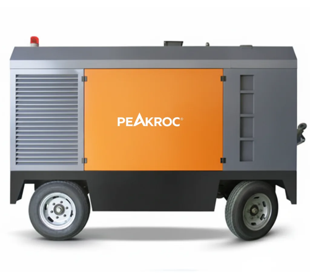
A 375–400 CFM machine is more likely to fit:
- Traditional telecom ducts
- Long routes with substantial airflow demand
- Blowers that require approximately 150–200 PSI
- Contractors serving several duct and cable combinations
- Utility fleets that also use the compressor for blasting or construction
It may be unnecessarily large for a compact microduct blower requiring only a small fraction of that airflow.
The quotation should identify FAD at the exact blower pressure, not merely the compressor’s maximum pressure. It should also include any pressure drop through the aftercooler, separator, filters, and delivery hose.
Why Aftercooling Matters for Cable Installation
Compression raises air temperature. As the air cools downstream, moisture condenses.
For cable blowing, hot or wet air can affect friction, lubrication, duct conditions, and installation consistency. The system may require an aftercooler, moisture separator, drain, and additional filtration or drying depending on the blower and project specification.
Air-treatment components also create pressure loss. A compressor that delivers 200 PSI at its outlet may deliver less at the blower after cooling, filtration, and a long hose run.
The supplier should state:
- Maximum air temperature after the cooler
- Pressure drop at rated flow
- Separator and drain configuration
- Required maintenance frequency
- Remaining FAD and pressure at the package outlet
Field Case: Urban Fibre-Blowing Work
Dutch telecom contractors APK Group CIAG and Ravesteijn Infra & Telecom use battery-powered Atlas Copco B-Air compressors for cable and conduit blowing. They cited low noise, zero local exhaust emissions, and independence from an external electrical supply as benefits for public-contract work.
The B-Air is smaller than the 375–400 CFM diesel class. The case demonstrates an important limitation of sizing only by maximum capacity:
Some fibre-blowing projects need less than 400 CFM, and urban operating conditions may make noise and emissions more important than maximum output.
A 400 CFM diesel machine can be technically capable but commercially unsuitable where the site restricts exhaust emissions or noise.
Sizing for Shotcrete
Shotcrete systems use compressed air to convey or atomise the wet or dry concrete mixture and project it against the receiving surface. The required air supply depends on the shotcrete machine, process type, hose arrangement, nozzle, material output, accelerator system, and whether other pneumatic equipment operates simultaneously.
Atlas Copco includes shotcrete among the applications for its 375–400 CFM, 100–200 PSI compressor range.
This does not mean every 400 CFM compressor will support every shotcrete machine.
Before selection, request the following from the equipment supplier:
- Minimum and recommended airflow
- Required pressure at the machine inlet
- Pressure required at the nozzle
- Maximum material-delivery rate
- Hose diameter and length
- Auxiliary air demand
- Expected continuous duty cycle
Underground shotcrete also introduces ventilation and emissions considerations. Atlas Copco reports that RVR Projects uses two electric E-Air units for shotcreting inside long tunnel sections on the Mumbai–Pune Expressway, where zero local exhaust emissions and lower noise improve working conditions.
The capacity of those units is not presented as a direct 400 CFM benchmark in the cited page. The case instead shows that two-machine configuration, air quality, ventilation, and redundancy may be more important than choosing one diesel compressor from a nominal flow class.
Sizing for Quarry Drilling
The phrase “quarry drilling” covers several different air requirements.
A 375–400 CFM machine may support:
- Handheld surface rock drills
- Pneumatic crawler drills
- Wagon drills
- Rock bolting
- Horizontal boring
- Drill flushing
- Selected small hammer systems
- General quarry maintenance air
Doosan positions its DA400—rated at 400 CFM and 175 PSI—for mechanised quarrying with pneumatic and hydraulic crawler drills as well as abrasive blasting. The machine is designed for hot and dusty operation and is offered with rough-terrain towing and a skid option.
Atlas Copco publishes surface rock-drill air consumption ranging from about 21 CFM for compact drills to approximately 106 CFM for the SRD 25. A 400 CFM machine can therefore support several suitable surface drills, subject to pressure, simultaneous use, hose loss, and flushing requirements.
Larger pneumatic underground drills can consume substantially more air. Atlas Copco lists approximately 69–97 litres per second at 6 bar for several pusher-leg models—roughly 146–206 CFM per drill.
A 400 CFM compressor may therefore support one or two such drills, but the actual combination must be checked carefully.
Why 400 CFM Is Not Automatically a DTH Compressor
DTH drilling requires both hammer-operating pressure and enough airflow to carry cuttings out of the borehole.
Deep water wells, large blast holes, high groundwater, and larger hammers commonly require substantially more than 400 CFM and pressures well above 200 PSI.
A 400 CFM, 175–200 PSI compressor should not be described as a general deep-DTH solution. It may suit a specific smaller hammer or shallow application only when the hammer manufacturer confirms:
- Minimum operating pressure
- Air consumption at that pressure
- Hole diameter
- Recommended compressor range
- Required cuttings velocity
- Maximum depth and backpressure conditions
Extra CFM cannot compensate for inadequate hammer pressure, and extra pressure cannot compensate for insufficient hole-cleaning velocity.
How Many Tools Can a 400 CFM Compressor Run?
There is no responsible single answer.
A practical tool-count calculation is:
Simultaneous tool demand =
Tool 1 rated consumption
+ Tool 2 rated consumption
+ Tool 3 rated consumption
+ all other active air consumers
Then adjust for:
- Continuous versus intermittent operation
- Tool wear and condition
- Lubricator and regulator losses
- Hose diameter and length
- Coupling restrictions
- Site conditions
- Required operating resilience
Consider three examples:
| Example | Theoretical demand | Initial assessment |
|---|---|---|
| Four 45.5 CFM efficient breakers | 182 CFM | Substantial capacity remains |
| Four 85 CFM heavy breakers | 340 CFM | Limited reserve for continuous operation |
| Three 85 CFM breakers plus one 51 CFM drill | 306 CFM | Possible with correctly designed distribution |
These are calculations based on published Atlas Copco tool-consumption figures, not guaranteed equipment combinations.
The tool manufacturer’s stated consumption and pressure should always take precedence.
Hose Size Can Decide Whether 400 CFM Reaches the Tool
At this flow level, an undersized hose can turn a correctly sized compressor into an underperforming system.
Pressure loss increases with:
- Greater airflow
- Longer hose runs
- Smaller internal diameter
- Rough or damaged hose walls
- Restrictive couplings
- Multiple bends
- Dirty filters
- Partially closed valves
The effect is especially important when one compressor supplies a manifold and several branches.
The operator should compare pressure at:
- The compressor outlet
- The manifold inlet
- Each branch
- The point of use under full demand
A normal compressor-outlet gauge combined with low tool pressure usually indicates distribution loss, excessive demand, or both.
Peakroc’s compressed-air system design article explains hose sizing, pressure drop, storage, and multi-user layouts in more detail.
Do Not Assume a Generic Capacity Margin
A fixed 20%, 25%, or 30% margin can be a convenient preliminary estimate, but it is not a substitute for engineering the uncertainty.
The correct allowance depends on the application.
A higher allowance may be justified when:
- Blast nozzles wear rapidly
- Rental customers connect unknown tools
- The site is hot or at high altitude
- Hose lengths change frequently
- Filters load quickly in dust
- Production cannot tolerate pressure loss
- Future equipment will be added
A smaller allowance may be reasonable when:
- One documented machine is permanently connected
- Demand is measured rather than estimated
- Hose dimensions are fixed
- Site conditions are mild
- The compressor has accurate variable-pressure control
- A standby machine is available
The goal is not maximum reserve. It is enough verified reserve to maintain production without paying for unnecessary capacity.
Altitude and Hot-Weather Performance
Sea-level catalogue output should not automatically be used for a high-altitude or high-temperature jobsite.
Lower air density can affect engine power, inlet mass flow, cooling, and the usable performance of the complete package. High ambient temperature reduces cooling margin and can increase the risk of temperature-related derating or shutdown.
Atlas Copco publishes a maximum ambient rating of 50°C for selected 375–400 CFM models. That is a model-specific rating, not a universal capability for every compressor in the class.
When requesting a quotation, provide:
- Site elevation
- Maximum ambient temperature
- Minimum starting temperature
- Relative humidity
- Dust level
- Hours per shift
- Expected continuous load
Ask the supplier to confirm FAD, engine power, cooling capability, and any derating at those conditions in writing.
Air Treatment Changes Available Output
An aftercooler, separator, filter, reheater, or dryer may be essential for blasting, coating, cable blowing, pipeline work, and temporary industrial air.
However, every component adds resistance.
The compressor quotation should show:
- FAD before treatment
- FAD after treatment where applicable
- Pressure drop at rated flow
- Outlet air temperature
- Moisture-removal performance
- Required drain arrangement
- Service intervals
For blasting, moisture can clog abrasive flow and oil may contaminate the prepared surface. Atlas Copco recommends appropriate aftercooling, filtration, and moisture control for demanding blasting applications.
A nominal 400 CFM package may therefore deliver less usable air after treatment. This loss must be included before the compressor is matched to a near-maximum-demand nozzle.
Fixed-Pressure or Variable-Pressure?
A fixed-pressure 375–400 CFM compressor is often appropriate when the machine performs one repeated task.
Examples include:
- One blasting setup at a fixed nozzle pressure
- One quarry drill
- One shotcrete machine
- A standard construction-tool fleet
Variable-pressure control is more valuable when one machine must serve several applications.
A rental company may use the same compressor for:
- 100 PSI construction tools
- 150 PSI abrasive blasting
- 175 PSI quarry support
- 200 PSI cable blowing
Atlas Copco and Bobcat both market adjustable or dual-pressure machines in this class as a way to increase application coverage and fleet utilisation.
Variable pressure does not remove the need to check FAD. The machine may provide different airflow at each pressure setting.
Comparing 8, 10, and 13 Bar Machines at Similar Flow
Peakroc publishes several compressors around the 10 m³/min class:
| Configuration | FAD | Pressure | Listed engine power |
|---|---|---|---|
| PRMD 10/8 | 10 m³/min | 8 bar | 81 kW |
| PRMD 10/10 | 10 m³/min | 10 bar | 97 kW |
| PRMD 10/13 | 10 m³/min | 13 bar | 110 kW |
The machines have similar nominal airflow but different engine-power requirements because producing the same flow at higher pressure requires more compression work.
This comparison illustrates why a buyer should not automatically select 13 bar when the application needs only 7–8 bar.
The higher-pressure package may offer useful flexibility, but it can also involve:
- Higher purchase cost
- Larger engine
- Greater fuel demand
- Higher hose and component pressure ratings
- Additional weight
- More capacity than the application can use
Fuel Consumption Should Be Linked to Productivity
Litres per hour is necessary for planning fuel supply, but it is not enough to compare project economics.
Use an application-specific metric:
Cost per productive unit =
Fuel
+ maintenance
+ ownership
+ mobilisation
+ downtime
÷ completed work
Possible productive units include:
- Square metres blasted
- Metres of cable installed
- Cubic metres of concrete removed
- Metres drilled
- Tonnes or batches of shotcrete applied
- Billable rental hours
A smaller compressor may burn less fuel per hour but increase labour time if tool pressure repeatedly falls.
A larger compressor may produce faster blasting but waste fuel when used for one small breaker.
Request fuel-consumption data at the actual pressure setting and expected load, not only at maximum output.
Rental-Fleet Considerations
The 375–400 CFM class can be valuable for rental companies because it covers the space between small construction compressors and large specialist machines.
Fleet managers should evaluate:
- Adjustable pressure range
- Frequency of customer misuse
- Control simplicity
- Telematics and fault history
- Trailer road compliance
- Service access
- Engine and filter commonality
- Fuel-tank endurance
- Aftercooler options
- Residual value
- Local parts support
Sullair’s 375H was developed for construction, abrasive blasting, fibre installation, and pipeline work, with a large fuel tank and service access aimed partly at rental users. Bobcat similarly positions its 400–450 CFM dual-pressure machine for multiple jobsite applications.
For rental fleets, a versatile pressure range can improve utilisation, but only when staff record which customers and applications require each setting.
Practical Selection Matrix
| Application | Is 375–400 CFM a plausible fit? | Main condition |
|---|---|---|
| Several pneumatic breakers | Yes | Add actual simultaneous tool consumption |
| One No. 8 blast nozzle | Often | Check wear, auxiliary demand, and nozzle pressure |
| Two No. 6 blast nozzles | Marginal | Nozzle demand may consume nearly all capacity |
| Traditional fibre cable blowing | Often | Match blower FAD and pressure |
| Small microduct blowing | Possibly oversized | May need higher pressure but much less flow |
| Selected shotcrete system | Possible | Obtain machine and nozzle requirements |
| Handheld quarry drills | Often | Confirm tool pressure and total consumption |
| Pneumatic crawler or wagon drill | Model-dependent | Use drill-manufacturer performance data |
| Shallow small-hammer drilling | Possible in limited cases | Hammer chart must approve |
| Deep water-well DTH drilling | Generally no | Usually requires greater pressure and airflow |
| General rental fleet | Strong potential | Variable pressure improves application coverage |
Common Selection Mistakes
Treating 400 CFM as Available at Every Pressure
Verify the pressure-flow curve. Some machines supply less than 400 CFM at their maximum pressure.
Selecting by Engine Horsepower
Engine power does not prove delivered airflow. Compare guaranteed package FAD at pressure.
Running a No. 8 Nozzle Without Wear Allowance
A new nozzle may fit the compressor, while the worn nozzle exceeds available capacity.
Raising Pressure to Correct a Small Hose
Higher compressor pressure does not remove a restrictive hose or coupling.
Calling Every 400 CFM Machine a Drilling Compressor
Quarry support and small drilling tools differ greatly from deep DTH and water-well drilling.
Ignoring Treatment-System Pressure Drop
An aftercooler and filters may be essential but reduce available pressure at the application.
Buying for the Largest Possible Job
A machine sized for an occasional peak may waste fuel and capital during routine work.
RFQ Checklist for a 375–400 CFM Compressor
| Required information | Why it matters |
|---|---|
| Application and connected equipment model | Establishes real demand |
| Required FAD at working pressure | Defines the operating point |
| Number of simultaneous tools | Determines combined airflow |
| Nozzle or tool condition | Accounts for wear |
| Hose diameter and length | Identifies pressure-loss risk |
| Air-treatment requirement | Adds pressure drop |
| Altitude and ambient temperature | Affects package performance |
| Hours per shift | Determines cooling and fuel needs |
| Required pressure range | Fixed versus variable-pressure selection |
| Chassis type | Trailer, skid, or truck integration |
| Emissions and noise limits | Determines engine and power-source suitability |
| Delivery destination | Determines compliance and logistics |
| Fuel price and productivity target | Supports operating-cost comparison |
| Required spare parts and warranty | Reduces lifecycle risk |
Peakroc’s compressor selection service can review these details before a final model is proposed.
Final Recommendation
Choose a 375–400 CFM portable diesel screw compressor when the application requires substantially more airflow than a 185–250 CFM machine but does not justify a larger 600 CFM package.
This class is particularly relevant for:
- Multi-tool construction crews
- One high-demand blast nozzle
- Traditional fibre-optic cable blowing
- Selected shotcrete equipment
- Pneumatic quarry tools
- Underground utility work
- Versatile rental fleets
Do not select it from the CFM label alone.
Confirm the FAD available at the required pressure. Add the true simultaneous tool or nozzle demand. Measure or calculate hose and treatment losses. Correct the machine selection for temperature, altitude, dust, and continuous duty. Finally, compare fuel cost per completed job rather than fuel consumption per hour alone.
A 400 CFM compressor is correctly sized when it maintains the required pressure and airflow at the point of use with enough documented reserve for the actual operating uncertainty.
It is undersized when the pressure collapses under continuous demand.
It is oversized when most of its capacity remains unused while fuel, transport, and ownership costs increase.
FAQ
What is 375 CFM in cubic metres per minute?
375 CFM is approximately 10.6 m³/min. A 400 CFM compressor supplies approximately 11.3 m³/min under its stated rating conditions.
Is a 375 CFM compressor the same as a 400 CFM compressor?
No. The nominal difference is about 25 CFM, but working pressure, control range, ambient rating, engine, airend, and FAD at maximum pressure may be more important than the nominal airflow difference.
Can a 400 CFM compressor run four jackhammers?
It may run four breakers when their combined air consumption remains below available FAD. Four 85 CFM breakers require about 340 CFM before hose losses and other demand, leaving limited reserve.
Is 400 CFM enough for sandblasting?
It can support one large nozzle in many applications. A No. 8 nozzle uses approximately 338 CFM at 100 PSI when new, leaving limited capacity for wear, losses, and auxiliary demand.
Can a 400 CFM compressor run two blast nozzles?
It depends on nozzle size. Two No. 5 nozzles may be feasible, while two No. 6 nozzles can consume close to the compressor’s entire capacity before losses and nozzle wear are included.
Is a 400 CFM compressor suitable for fibre-optic cable blowing?
It can suit traditional ducts and blowers requiring substantial airflow at approximately 150–200 PSI. Small microduct equipment may require much less airflow and could make a 400 CFM machine unnecessarily large.
Can a 400 CFM compressor be used for DTH drilling?
Only for a specifically approved small or shallow hammer system. It is generally not sufficient for deep water-well drilling or large DTH hammers requiring higher pressure and airflow.
Should I choose 100, 150, 175, or 200 PSI?
Choose the pressure required at the point of use after hose and treatment losses. Construction tools commonly use the lower range, while blasting, utility work, cable blowing, and selected drilling equipment may require higher pressure.
Does a 400 CFM compressor always deliver 400 CFM at 200 PSI?
No. Some variable-pressure machines deliver less airflow at their maximum pressure. Request the guaranteed pressure-flow table from the supplier.
Is a variable-pressure compressor better for rental fleets?
It can improve utilisation because one machine can serve several applications. The fleet must still confirm FAD at every pressure setting and train users to select the correct operating point.
Author

Mark Chen – Senior Mechanical Engineer, Peakroc®
Mark Chen is a senior mechanical engineer at Peakroc®, specializing in compressed air systems and drilling equipment for mining and construction applications. With over 15 years of field experience, he has led multiple projects on optimizing air delivery efficiency, equipment durability, and energy consumption.